This is an update to several previous blog posts and will encapsulate a ton of information on my quadcopter project. It is still not flying yet, but we're close! Most of this work was done over the past year but I have not had the time to post an update since I've been busy with work/school/life.
My goals for the project were:
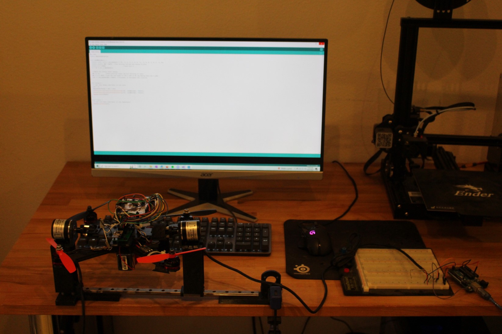
Here is a current pic of the design and solution I have made:
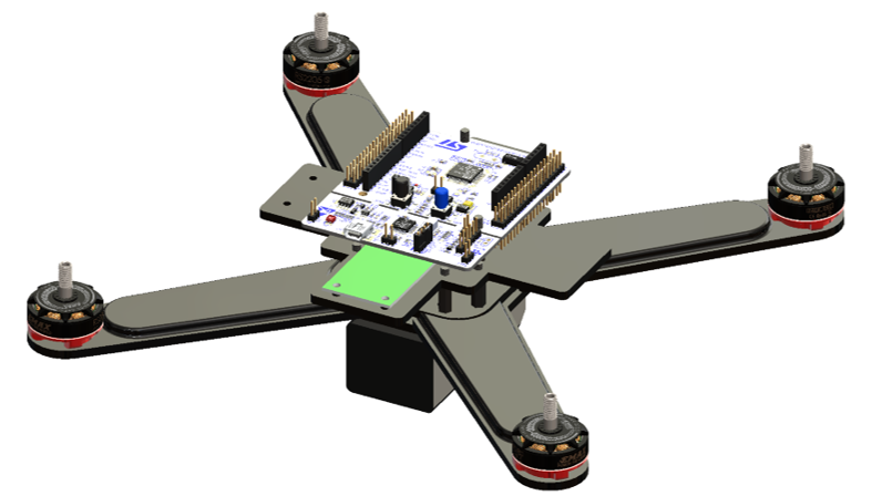
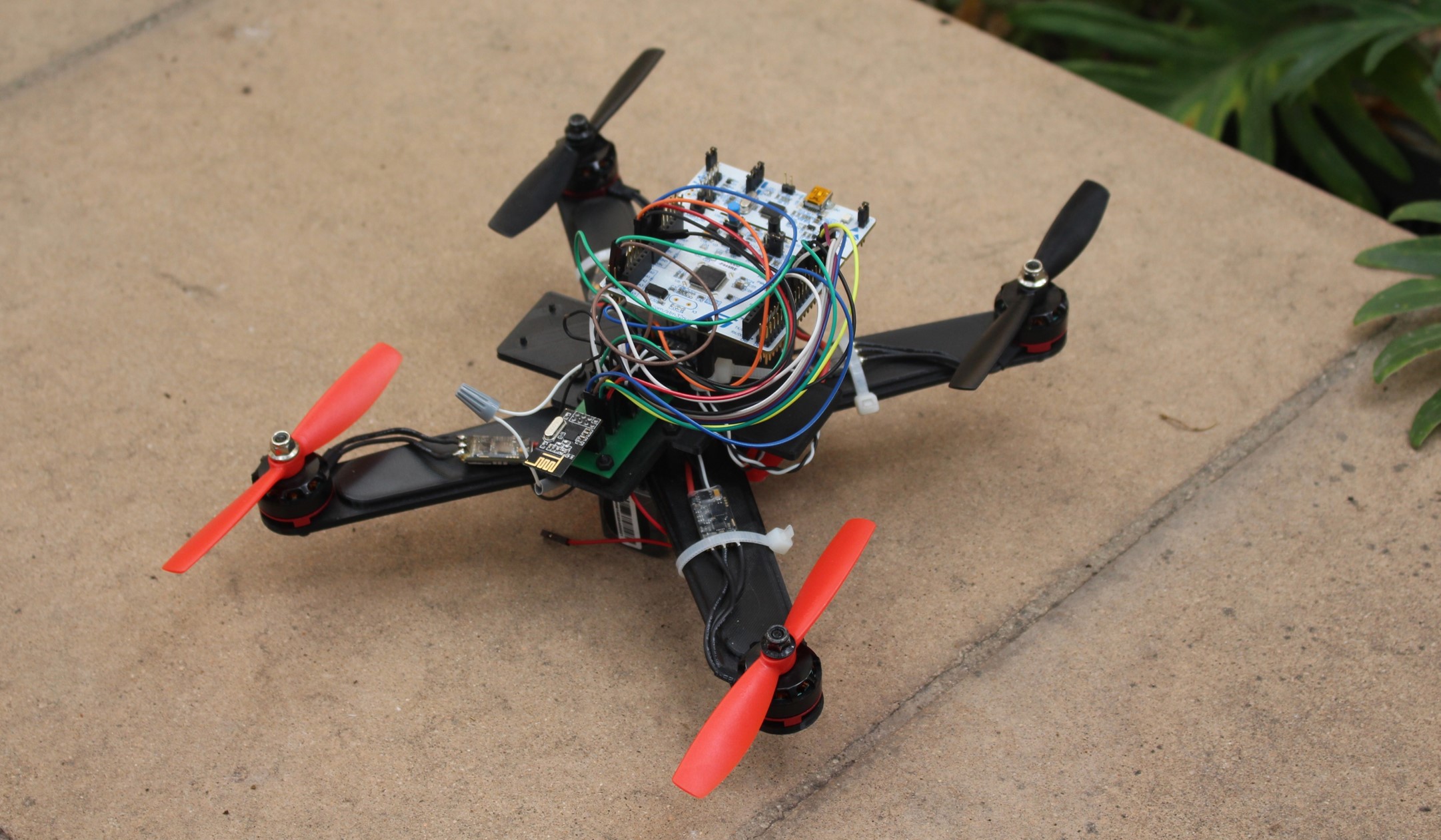
All of the mechanical parts are 3D printed on my Ender-3 Pro. The mechanical design I chose was to separate the quadcopter into layers separated by nylon standoffs. The lower layer would house the power electronics. The second layer would hold the sensor boards and also had mounting points for future test fixturing. The upper layer would be the MCU board - it would rest directly on the nylon standoffs. The quadcopters battery would be held in place by velcro-straps that weaved through the lowest-level of the board; I placed it here since I thought it was going to be the heaviest component of the system and would therefore help stabilize the quadcopter in the lower position.
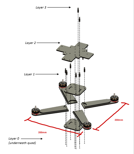
The arms of the quadcopter are printed at 100% fill and are thicker than most other layers; the quadcopter motors are powerful and I previously had an accident where one of the motors snapped an arm at low-throttle. They are designed to place the motors in a standard 200 mm x 200 mm configuration.
Here's a nice breakout of the design:
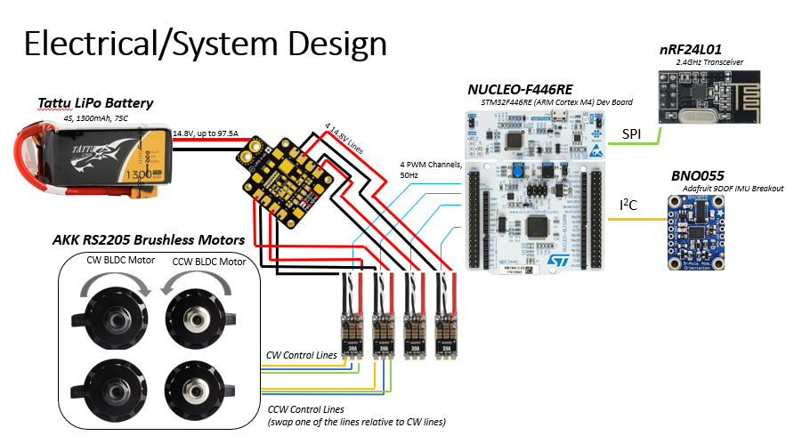
The electrical system is fairly standard for a quadcopter. All of the power electronics chosen were cheap parts off of amazon. The ESC's I chose would accept a PWM input though - since I figured that would be easier to write software against as opposed to a custom protocol.
The MCU board chosen was a NUCLEO-F446RE - it was a cheap ARM board on Amazon - I wanted to step into the ARM ecosystem for this project. The IMU I selected is kind of fancy - it is a 9DOF IMU board from Adafruit with sensor fusion built in; it has a gyroscope, magnetometer, and accelerometer built in. It has its own onboard MCU that is running sensor fusion. The MCU can be configured to give out raw output as well, but I am currently using it in the 9DOF-fusion mode. For remote comms I selected a NRF radio board that had a SPI interface.
Here is a good diagram of all the components:
The flight control software is all in C++. It uses FreeRTOS as well. There are 3 main threads within the software - the IMU/sensor thread, the Control thread, and the Motor actuation thread. The software is multithreaded to accomodate for the different sampling/actuation/control loop rates of the system. Simple drivers for the IMU and comms board were written that wrap all of the SPI and I2C library calls.
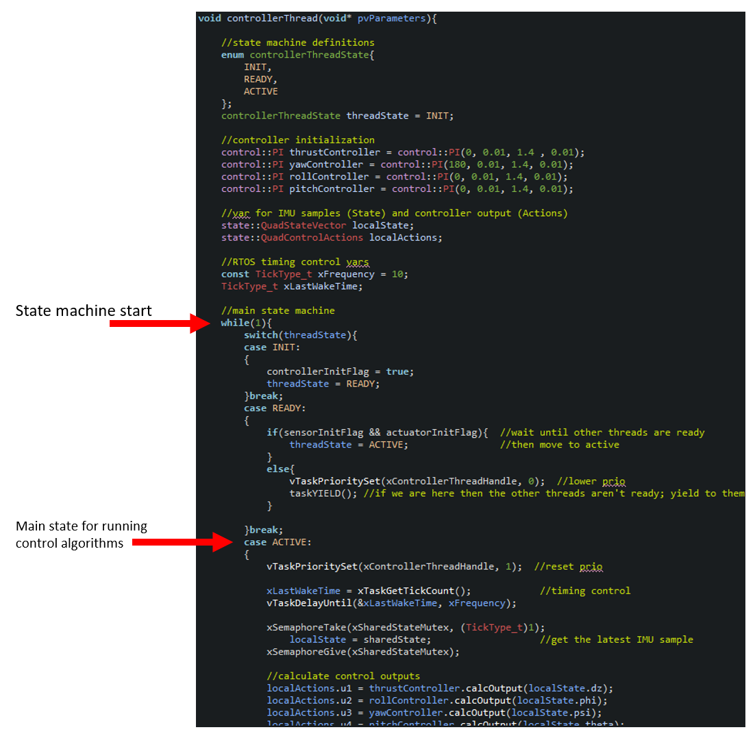
All three threads are state machines. They will go through some initial stages that block and configure their respective hardware, and once everything is in place the Quad will beep loudly before starting the full closed loop control. Here's a look at the controller thread:
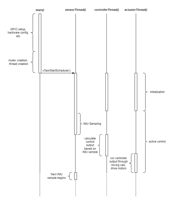
The sensor thread is the main producer of the system. It's consumer is the controller thread - who will produce the output for the actuator thread. The sensorThread() will block the system from reaching an active control state until the IMU feels that it has reached full calibration (the IMU will self-calibrate as you move the quad around). Here is a sequence diagram showing the main execution order of the flight controller:
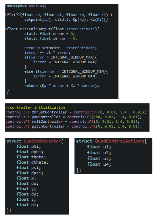
For the control algorithm, 4 PI controllers are used for each of the control variables (note: only 4 variables of the quad system are under active control: thrust, pitch, yaw, and roll. The quadrotor is underactuated). Structs are utilized to store the system's state information, and the output of the control algorithms. The structs are shared between threads.
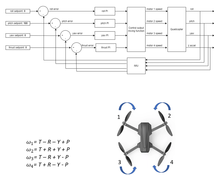
As stated in the software section - 4 variables are under active control in the system; thrust, pitch, roll, and yaw. They are controlled via PI controllers since PI is all that is needed to guarantee stability (for linear systems). The outputs of the PI controllers are then input into a control mixing function in order to send the proper outputs to the motors as shown below:
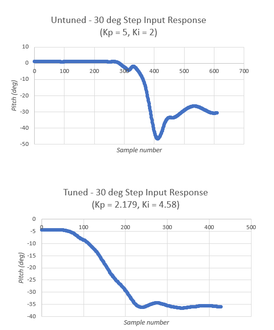
For tuning and testing of the controllers I developed a simple test fixture for the quadcopter. The test fixture consisted of two elevated rotary encoders that could attach to either side of the quad and suspend it such that it could freely rotate on its roll/pitch axis. Within the flight software I would send in a step-control input, and then use the test fixture to measure it's response and tune the controller.
Some plots of the test results are shown below - an un-tuned step response is at the top of the figure, and a tuned step response is at the bottom. A ziegler-nichols tuning method was used to calculate the appropriate gains for the system:
The quadcopter can now fully sense and actuate its motors - the closed loop control is generally working. However, the flight is still not stable. The thrust controller (since acceleration is a second derivative) needs additional testing to dial the system in (missing the "+ c" constant acceleration needed for minimal thrust). Additionally, the IMU seems to have some drift within it's measurements, so that will require some more testing as well (and maybe a purchase of another board). Anyways, I have learned a ton on the project so far, and it is close to being done - just needs a few more months of work.
Here is a short video showing it in an active control state: