Like most engineers, when I want to build a project, I have an impulse to recreate everything from scratch. When I was working on my inverted pendulum, I wanted to break free from the comfortable Arduino IDE and I wrote my own low-level, embedded C. This weekend, for my quadcopter project, I thought I would attempt something similar, and hopped into Keil to write bare-metal code for the flight controller. While this is great for learning about some of the software and hardware that underpins our high-tech society, it takes a great deal of time and effort as the layers-of-abstraction are all out the window.
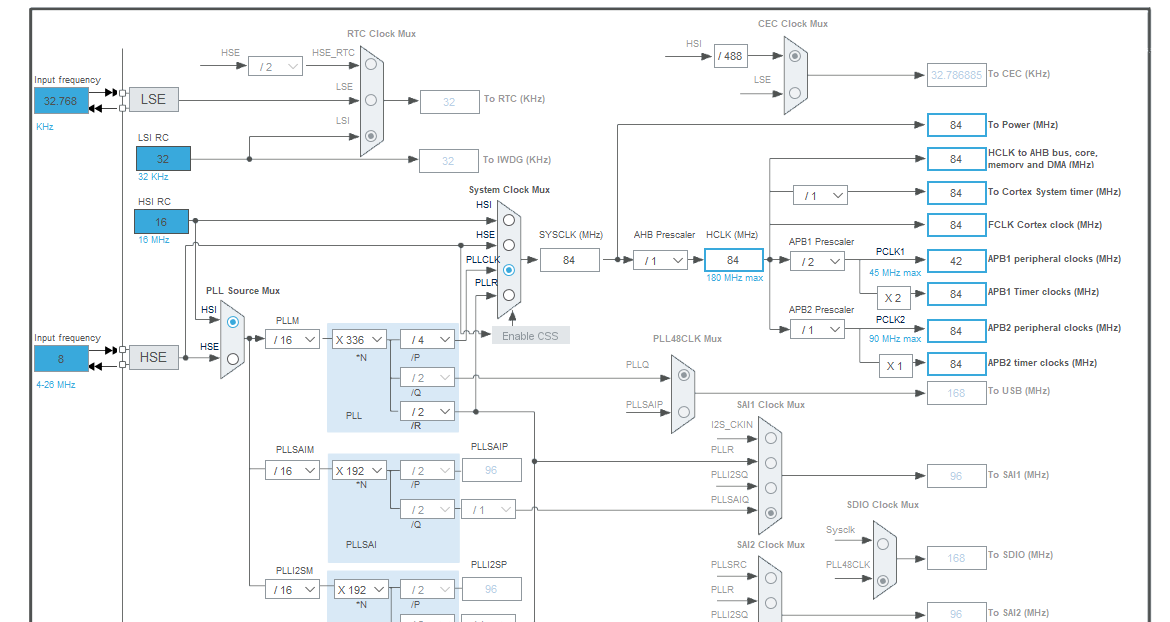
On Saturday morning I popped Keil open. Excited and full of energy to get this quadcopter to first-hover, I started to code the flight control software. I knew that writing low-level firmware is difficult (I have written some low-level code for AVR microcontrollers in the past), but I dramatically underestimated the complexity of this STM32F4 chip. The STM32CubeIDE allowed me to configure all of the system clocks I needed with a GUI interface - with Keil I had to consult the datasheet, write registers, check the CMSIS header definitions, and debug. Below is a nice pic of the STM32CubeIDE GUI being used to configure the system clock, followed by 30 lines of C code that performs the same function:
STM32CubeIDE Clock Configuration
    void BSP_Clock_Configuration(void){

    	//turning the HSI on, wait for ready
    	RCC->CR |= ((uint32_t) RCC_CR_HSION);
    	while((RCC->CR & RCC_CR_HSIRDY) == 0);

    	RCC->CFGR = RCC_CFGR_SW_HSI;      /* HSI is system clock */
            while ((RCC->CFGR & RCC_CFGR_SWS) != RCC_CFGR_SWS_HSI);  /* Wait for HSI used as system clock */
    	//configure the PLL
    	RCC->PLLCFGR |= RCC_PLLCFGR_PLLSRC_HSI;	//sets the PLL input to the HSI
    	RCC->PLLCFGR |= RCC_PLLCFGR_PLLM_4; 	//divides by 16
    	RCC->PLLCFGR |= (0xD0UL << RCC_PLLCFGR_PLLN_Pos); //logic for this in a spreadsheet

    	RCC->PLLCFGR |= RCC_PLLCFGR_PLLP_0;	//divides by 4

    	//turn off some of the default PLL configuration
    	RCC->PLLCFGR &= ~RCC_PLLCFGR_PLLN_6;

    	//enable PLL, wait for ready
    	RCC->CR |= RCC_CR_PLLON;
    	while((RCC->CR & RCC_CR_PLLRDY) == 0);

    	//set the sysclk mux to take from the PLL
    	RCC->CFGR &= ~RCC_CFGR_SW;
    	RCC->CFGR |=  RCC_CFGR_SW_PLL;

    	//wait for PLL to become sysclk source
    	while((RCC->CFGR & RCC_CFGR_SWS) != RCC_CFGR_SWS_PLL);

    }
Thats about 30 full lines of code to setup the clock. Compare this to the timer setup code for an AVR microcontroller:
The difference is stark. The GUI of the STM32F4 clock control does however, demonstrate the complexity, and flexibility of the M4 chip. While setting up the timing hardware and reading the datasheets was a challenge, I think I will go back to the STM32CubeIDE for setup. For code running in production, I think writing the low-level CMSIS code could be worthwhile, but for home projects, where time is very limited, using every tool possible to bring simplicity to the project is very important.
Here are two more great comparisons between the AVR microcontroller code, and STM32F4 code that serves the same function. The first 2 code snippets show the configuration of a GPIO port, and the second 2 snippets show the configuration of PWM:
ATMega328P GPIO Setup Code (AVR Chip)
    void rotary_encoders_setup(){
    	//Set up PORTD to accept the rotary encoder data
    	PCICR |= _BV(PCIE2);  //turn on interrupt
    	PCMSK2 |= _BV(PCINT21) | _BV(PCINT20) | _BV(PCINT19) | _BV(PCINT18); // enable pins on interrupt
    	DDRD = 0b11000000;                   //all pins on Port B are inputs except for PD7/6
    	PORTD = 0b00111100;                  //pullups for portD0, portD1, portD2, portD3
    	PIND = 0b11000000;					 //release the brakes
    }
STM32F4 GPIO Setup Code
    void BSP_GPIO_Configuration(void){
    	//configure GPIOA

    	//enable AHB clock for GPIOA
    	RCC->AHB1ENR |= RCC_AHB1ENR_GPIOAEN;
    	__DSB();  //delay after peripheral enables per product errata datasheet


    	//GPIO MODER register sets the GPIOA to
    	//"alternate function" mode.  The PWM
    	//that is coming off the timer is considered an
    	//"alternate mode"
    	GPIOA->MODER |= GPIO_MODER_MODER11_1;
    	GPIOA->MODER |= GPIO_MODER_MODER10_1;
    	GPIOA->MODER |= GPIO_MODER_MODER9_1;
    	GPIOA->MODER |= GPIO_MODER_MODER8_1;

    	//select the pull-up/pull-down type, output speed,
    	//etc for the periphral

    	//push pull is default

    	//set pull to pull-up
    	GPIOA->PUPDR |= GPIO_PUPDR_PUPDR11_0;
    	GPIOA->PUPDR |= GPIO_PUPDR_PUPDR10_0;
    	GPIOA->PUPDR |= GPIO_PUPDR_PUPDR9_0;
    	GPIOA->PUPDR |= GPIO_PUPDR_PUPDR8_0;


    	//set speed to high
    	//3U for high mode
    	GPIOA->OSPEEDR |= GPIO_OSPEEDR_OSPEED11;  //by default this is 3U bit shifted to pos
    	GPIOA->OSPEEDR |= GPIO_OSPEEDR_OSPEED10;
    	GPIOA->OSPEEDR |= GPIO_OSPEEDR_OSPEED9;
    	GPIOA->OSPEEDR |= GPIO_OSPEEDR_OSPEED8;

    	//attach the GPIO pin to the timer peripheral
    	//by altering the "GPIOA->AFRH" register,
    	//this will alter a MUX that goes to the GPIO.
    	//0x0001 => AF1 => TIM1, and the "AFRH" works on pins
    	//A8 to A15
    	//AFR[1] here is the AFRH
    	GPIOA->AFR[1] |= 0x0001 << GPIO_AFRH_AFSEL11_Pos;
    	GPIOA->AFR[1] |= 0x0001 << GPIO_AFRH_AFSEL10_Pos;
    	GPIOA->AFR[1] |= 0x0001 << GPIO_AFRH_AFSEL9_Pos;
    	GPIOA->AFR[1] |= 0x0001 << GPIO_AFRH_AFSEL8_Pos;

    	//configure GPIOB

    }
ATMega328P PWM Setup Code
    void motor_setup(){
    	//Set up PWM
    	TCCR1A |= _BV(COM1A1) | _BV(WGM11) | _BV(WGM10);
    	TCCR1B |= _BV(CS10);
    	OCR1A = 0x03ff;			//10-bit compare register, initially set at maximum
    	DDRB = 0b0010010;		//pin 9 (PB1) is PWM, output, PB4 is status LED (red) control

    	//Motor direction control on PORTC
    	DDRC = 0b00000011;
    }
STM32F4 PWM Setup Code:
    void BSP_Timer_PWM_Configuration(void){

    	/*Quadcopter ESCs have their own uC's that have
    	 *multiple different comm protocols to control them
    	 *oneshot, etc.  ESCs typically also accept a 50 Hz PWM
    	 *signal.  Currently this function will configure the
    	 *timer counter to generate a 50 Hz PWM signal
    	 */

    	//enable SYSCLK for timer 1 on APB2
    	RCC->APB2ENR |= RCC_APB2ENR_TIM1EN;
    	__DSB();  //delay after peripheral enables per product errata datasheet

    	//use prescaler to divide incoming 84 Mhz clock
    	//freq_tim1 = freq_clk / (psc + 1)
    	TIM1->PSC = 12UL;

    	//start at 0, the auto-reload is set s.t.
    	//the counter will overflow at 62677
    	//this is so the PWM hits the target rate of 50 Hz
    	//might implement the calculation here eventually,
    	//currently have a spreadsheet running these timer
    	//calcs
    	TIM1->CNT = 0UL;
    	TIM1->ARR = 56602UL;
    	TIM1->RCR = 0UL;	//0 for RCR should force register reloads on every eupdate event

    	//set some default values here for signals
    	TIM1->CCR1 = 2000UL;
    	TIM1->CCR2 = 2000UL;
    	TIM1->CCR3 = 2000UL;
    	TIM1->CCR4 = 2000UL;

    	//enable preloading
    	TIM1->CR1 |= TIM_CR1_ARPE;
    	TIM1->CCMR1 |= TIM_CCMR1_OC1PE;
    	TIM1->CCMR1 |= TIM_CCMR1_OC2PE;
    	TIM1->CCMR2 |= TIM_CCMR2_OC3PE;
    	TIM1->CCMR2 |= TIM_CCMR2_OC4PE;

    	//ensure channels are configured as outputs
    	TIM1->CCMR1 &= ~TIM_CCMR1_CC1S;  //turns off these bits
    	TIM1->CCMR1 &= ~TIM_CCMR1_CC2S;
    	TIM1->CCMR2 &= ~TIM_CCMR2_CC3S;
    	TIM1->CCMR2 &= ~TIM_CCMR2_CC4S;

    	//configure the PWM mode
    	TIM1->CCMR1 |= (6UL << TIM_CCMR1_OC1M_Pos); //0x110 triggers PWM mode 1
    	TIM1->CCMR1 |= (6UL << TIM_CCMR1_OC2M_Pos);
    	TIM1->CCMR2 |= (6UL << TIM_CCMR2_OC3M_Pos);
    	TIM1->CCMR2 |= (6UL << TIM_CCMR2_OC4M_Pos);

    	//enable outputs on the physical pins
    	TIM1->CCER |= TIM_CCER_CC1E;
    	TIM1->CCER |= TIM_CCER_CC2E;
    	TIM1->CCER |= TIM_CCER_CC3E;
    	TIM1->CCER |= TIM_CCER_CC4E;

    	//preloads are transferred to shadow registers only when
    	//an update event occurs according to docs, so
    	//need to initialize all the regs we just set
    	//by "setting the UG bit in the TIMx_EGR" reg
    	TIM1->EGR |= TIM_EGR_UG;

    	//set the main output enable bit
    	TIM1->BDTR |= TIM_BDTR_MOE;

    	//this will select the internal clock as the counter
    	//source and start the output compare mode
    	TIM1->CR1 |= TIM_CR1_CEN;

    }
The more powerful hardware of the STM32F4 introduced a lot of complexity - complexity which I am definitely looking to avoid (haha).
The point of my quadcopter project is to write, and therefore learn, advanced control algorithms, not become an embedded systems engineer. My time would have been much better spent this weekend implementing a Kalman filter, and not attempting to setup timer/counter hardware.
This experience was worthwhile however, as I further sharped my understanding of microcontroller architecture and hardware, but next weekend I will absolutely be using the STM32CubeIDE to generate all of my hardware configuration code for me.
While I was writing the bare-metal code, I was constantly reminded of the following quote from Carl Sagan, from which I drew the title of this post:
"If you wish to make an apple pie from scratch, you must first invent the universe."
Edit 2/16/2021: On second thought, I think I will continue to write most of my own firmware. I can introduce abstractions as the CMSIS setup code becomes more complex, there are only 2 peripherals more left to set up. CMSIS has some driver libraries for I2C and SPI, so this should not be too bad. If anything, this will be a nice programming challenge; I will hopefully learn better program architecture/structure and in the end maintain full control of my board and peripherals.
Published on Feb. 16, 2021, 5:51 a.m.