With so much information readily available on the internet I never feel like I have an excuse for not challenging my design skills on a project. Granted, most of the information on the internet is low-quality, but if you have a good filter you can normally find some high quality information fast. For some high quality PCB basics content I would highly recommend Phil's Lab on youtube (https://www.youtube.com/user/menuuzer, philsal.co.uk). I have basically learned all of my PCB design from this guy.
Anyways, here is the PCB that I was able to design in KiCAD over a weekend:
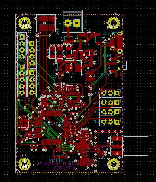
Power circuitry is located at the top of the board. The uC is located at the bottom left. The WiFi radio is on the bottom right. The accelerometer is in the very center (need it to centered in order to have accurate gyro measurements). I have broken out all of the communication lines that are active on the uC to pin headers on the left, and the motor PWMs are all on pin headers on the right.
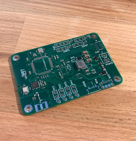
It is so surprising how easy it was to get this made, with SMD components too! JLCPCB made 5 copies for me for about $50. An American fab quoted me over $1100 for the same service. Due to the chip shortage though, not all of the parts were immediately available. I ordered some STM32F4 dev boards and will scavenge the uC's off of them with a heat gun. For the components that were not placed by JLCPCB, I will reflow solder those with a heat gun as well.
The PCB has arrived! Very proud of this first design:
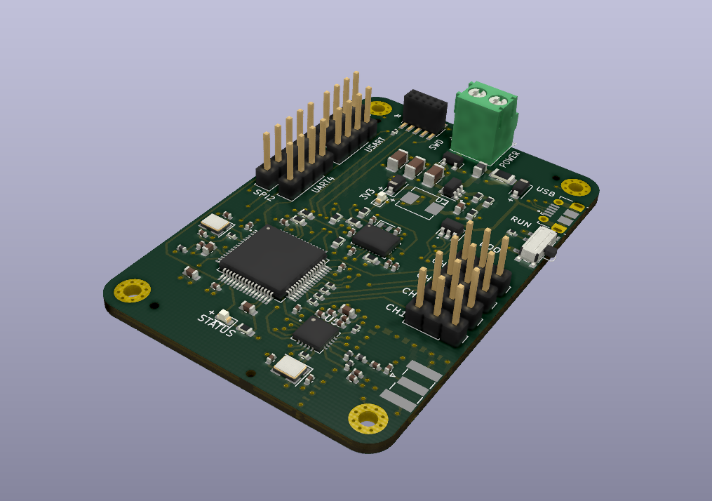
Here is a render from KiCAD that has more of the components shown:
Published on July 31, 2021, 5:46 p.m.